ContWhat is MIM Technology and Why Does It Matter?

Manufacturing small, complex metal parts with high precision often forces engineers into a tough compromise. Traditional CNC machining delivers excellent accuracy but generates high material waste and skyrocketing labor costs at scale. On the other hand, conventional casting reduces material loss but struggles with intricate geometries and strict tolerances.
This dilemma leads directly to the core question: what is MIM technology, and how does it solve this production bottleneck?
Metal Injection Molding (MIM) is an advanced manufacturing process that combines the geometric design freedom of plastic injection molding with the material strength and thermal properties of traditional metallurgy. By combining fine metal powders with a polymer binder, MIM enables high-volume production of complex, net-shape metal components that would be difficult or cost-prohibitive to machine using standard methods.
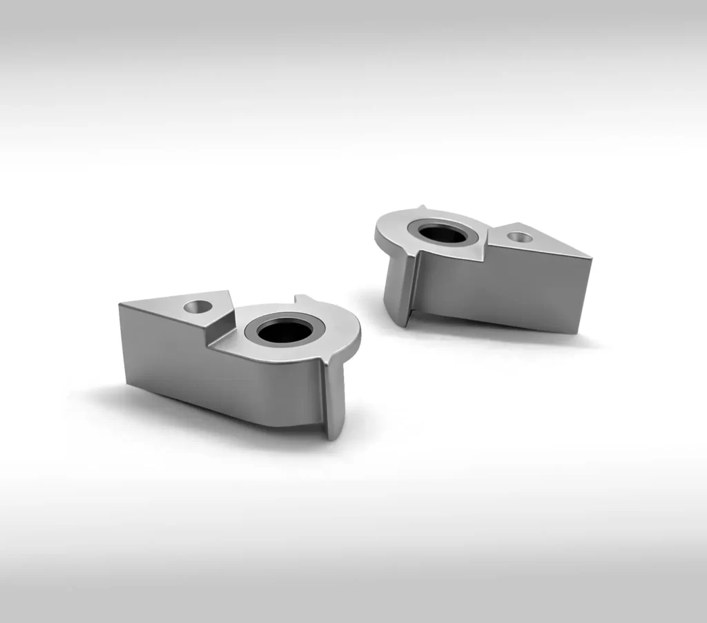
How Metal Injection Molding Works: 4-Step Process
The MIM process transforms raw metal powder into a high-density, high-precision final component through four critical manufacturing phases:
1. Feedstock Preparation:Mixing metal powder with polymer binders。
Fine spherical metal powders (typically smaller than 20 microns) are homogeneously mixed with a thermoplastic binder system (waxes and polymers). The mixture is heated and granulated into uniform pellets known as feedstock.
2. Injection Molding:Forming the green part。
The feedstock pellets are fed into a standard injection molding machine. Heat melts the binder, allowing the viscous material to fill a hardened steel mold cavity under high pressure. The cooled, ejected part is known as a "green part."
3. Debinding:Removing the primary binder。
The binder system is extracted from the green part using thermal processing, chemical solvents, or catalytic processes. Once the majority of the binder is removed, the remaining porous structure is called a "brown part."
4. Sintering:Densifying the metal matrix。
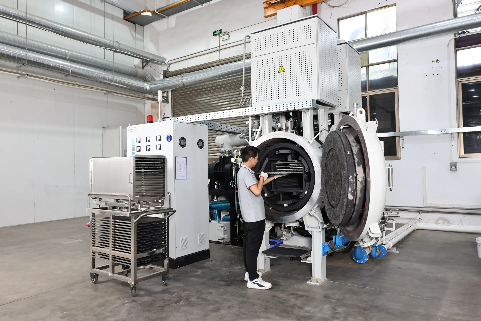
The brown part is placed in a high-temperature atmosphere or vacuum furnace. Temperatures are elevated to near the metal's melting point (typically 1200°C to 1400°C). The remaining binder burns off, and the metal particles fuse together, resulting in a dense metal component with up to 96%–99% theoretical density.
Note on Shrinkage: During sintering, parts shrink predictably by 15% to 20% as pores close and particles consolidate. Precision mold tooling compensates for this shrinkage up front to maintain tight final dimensions.
MIM vs Traditional Manufacturing (CNC Machining & Investment Casting)
Choosing the right process depends heavily on volume, geometry complexity, and production budget. The breakdown below highlights how MIM compares directly with CNC machining and investment casting:
| Feature / Metric | Metal Injection Molding (MIM) | CNC Machining | Investment Casting |
| Optimal Production Volume | High (10,000 to 1,000,000+ units) | Low to Medium (1 to 5,000 units) | Medium to High (1,000 to 50,000 units) |
| Geometric Complexity | Extremely High (Undercuts, internal threads) | Moderate (Limited by tool access) | High (Requires core assembly) |
| Material Utilization | High (~95% raw material yield) | Low (Heavy chip creation/waste) | Moderate |
| Part Weight Limit | Best under 100 grams | Virtually unlimited | Up to 50+ kilograms |
| Dimensional Tolerance | ±0.3% to ±0.5% | ±0.005 mm to ±0.05 mm | ±0.5% to ±1.0% |
| Initial Tooling Cost | High ($5,000 – $30,000+) | Low (No custom molds) | Moderate |
Key Advantages of Metal Injection Molding
When evaluated against traditional production paths, MIM delivers several distinct technical and commercial benefits:
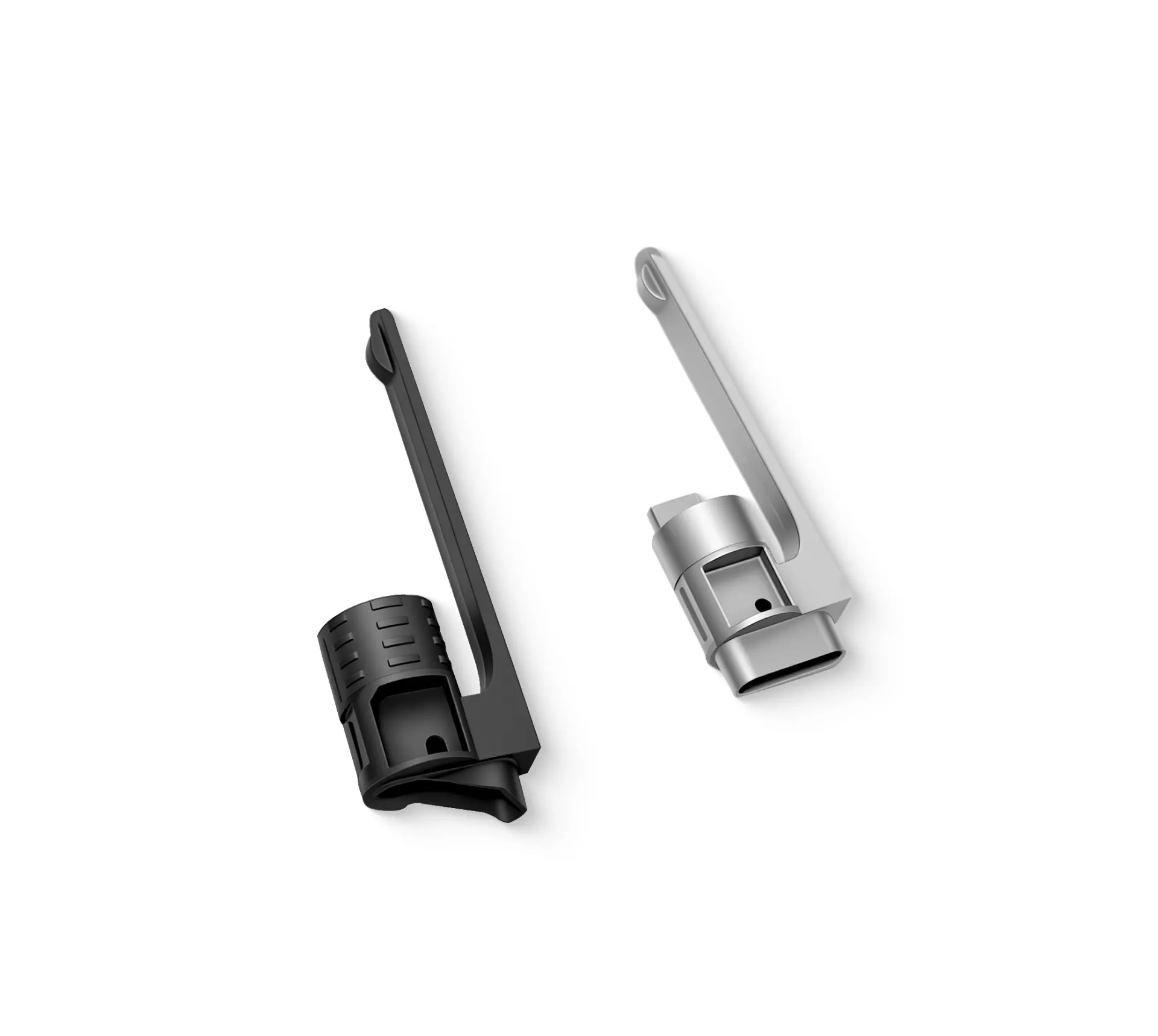
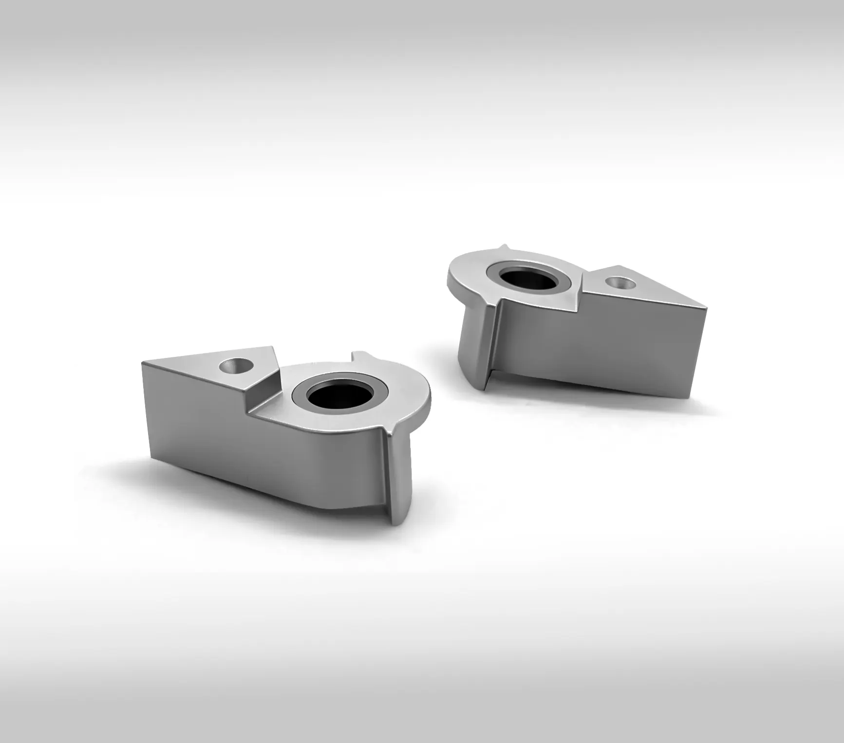
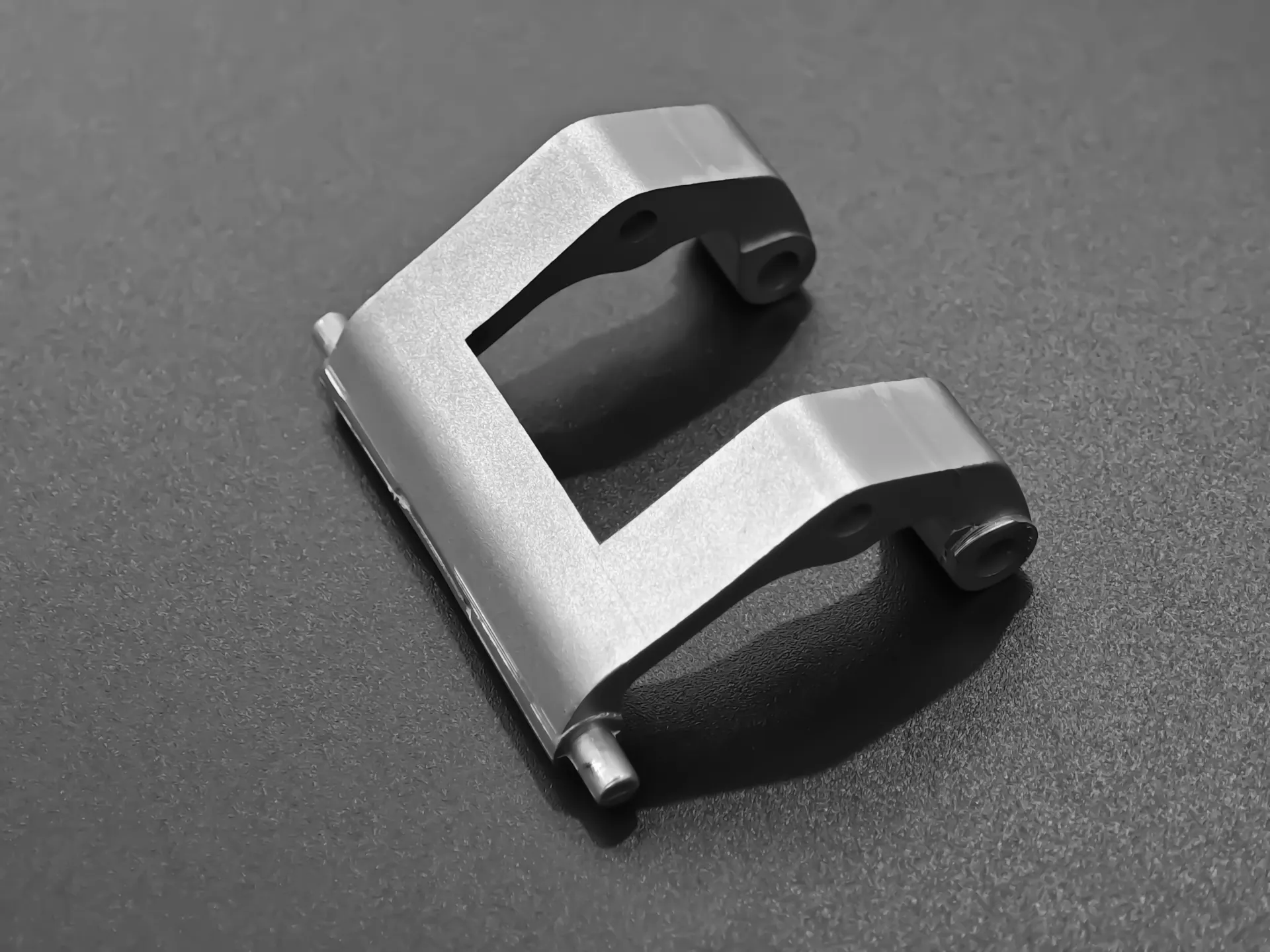
Unmatched Design Freedom: Enables complex features such as internal threads, knurling, cross-holes, thin walls, and external branding directly into the mold without secondary machining.
Superior Material Density: Sintered MIM parts achieve 96% to 99% of theoretical density, delivering mechanical properties (tensile strength, hardness, corrosion resistance) equivalent to wrought metals.
Cost Efficiency at Scale: High upfront mold investments yield significantly lower per-unit production costs for mid-to-high volume runs.
Minimal Material Waste: Unused feedstock and molding runners can often be recycled back into the production stream, drastically reducing scrap expenses on high-cost alloys like titanium or cobalt-chrome.
Common Materials Used in MIM
MIM accommodates a wide array of ferrous and non-ferrous metal alloys:
Stainless Steels: 316L, 17-4PH, 304L, 420 (Ideal for medical devices, consumer electronics, marine components).
Low Alloy Steels: 4140, 8620, 2200 (Commonly selected for high-strength automotive and structural components requiring heat treatment).
Tool Steels: M2, M4, S7 (Selected for high-wear industrial tools and cutter heads).
Specialty Alloys: Titanium alloys (Ti-6Al-4V), Cobalt-Chromium, Kovar, Inconel (Used in aerospace, medical implants, and thermal management hardware).
Top Industry Applications
The unique properties of MIM make it an ideal fit across high-precision industries:
| MIM APPLICATIONS | |||
| Automotive | Medical & Dental | Consumer Devices | Aerospace/Defense |
| Turbocharger | Surgical scalpels | Smartphone hinges | Missile fins |
| vanes | Orthodontic | Smartwatch | Engine ignition |
| Fuel injectors | brackets | casings | components |
| Door lock | Endoscopic | Camera lens | Fastener |
| mechanisms | tools | mounts | hardware |
Critical Design Guidelines & Common Pitfalls
While MIM offers tremendous design flexibility, ignoring process constraints can cause part warping, voids, or unexpected tooling costs.
Essential Design Rules
Maintain Uniform Wall Thickness: Aim for wall thicknesses between 1.0 mm and 3.0 mm. Non-uniform sections create differential cooling rates, leading to sink marks and internal voids.
Incorporate Draft Angles: Include a 0.5° to 1° draft angle to allow smooth ejection from the mold without dragging or deforming the green part.
Use Generous Radii: Avoid sharp internal corners. Internal fillets (minimum 0.5 mm radius) distribute mechanical stress and improve feedstock flow during injection.
Avoid These Common Pitfalls
Over-specifying Heavy Parts: MIM is cost-ineffective for heavy, blocky components (over 150 grams). Consider coring out thick sections to save weight and maintain uniform walls.
Ignoring Sintering Support: Parts require flat surfaces or dedicated ceramic fixtures to support them during high-temperature sintering. Designing flat resting points prevents sagging.
Expecting Machined Tolerances Out of the Furnace: Standard MIM tolerances sit at ±0.3% to ±0.5%. If your design requires sub-micron precision on select features, plan for minor post-sintering CNC sizing or grinding.
Understanding what MIM technology is opens up significant design opportunities for hardware engineers and supply chain managers. By blending the geometric versatility of plastic molding with the structural performance of metal, MIM delivers precision, strength, and unit-cost reduction for high-volume component production.
Frequently Asked Questions (FAQ)
What is the difference between MIM and traditional Powder Metallurgy (PM)?
Press-and-sinter Powder Metallurgy uses mechanical presses to compact coarse metal powder uni-axially, limiting parts to simpler, 2D shapes. MIM uses fine metal powder mixed with binder in an injection molding setup, allowing full 3D design complexity, undercuts, and higher final density.
Is MIM suitable for low-volume production runs?
Generally, no. Because MIM requires custom steel molds that cost thousands of dollars, it is rarely cost-effective for runs under 5,000 pieces. For low volumes, 3D printing (Metal Binder Jetting) or CNC machining is more economical.
How strong are MIM components compared to machined parts?
MIM parts achieve 96% to 99% of the density of wrought metal. As a result, their mechanical properties—including tensile strength, yield strength, and fatigue life—are virtually indistinguishable from machined or forged equivalents.
Learn more about related knowledge
Share on Social: