MIM Automotive Sensor Housings: Complete Guide & Sourcing Insights
By Yizejing
09, 2026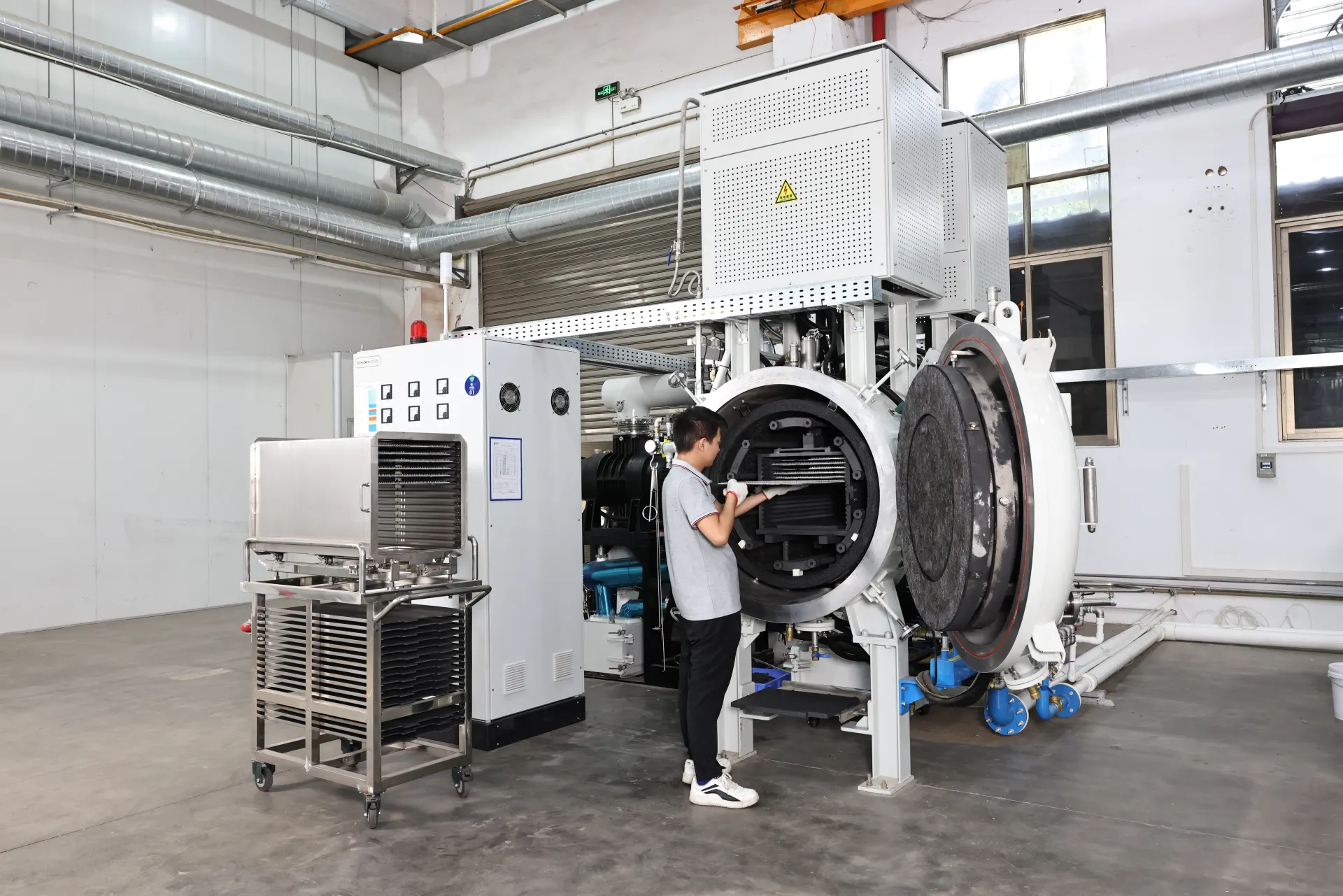
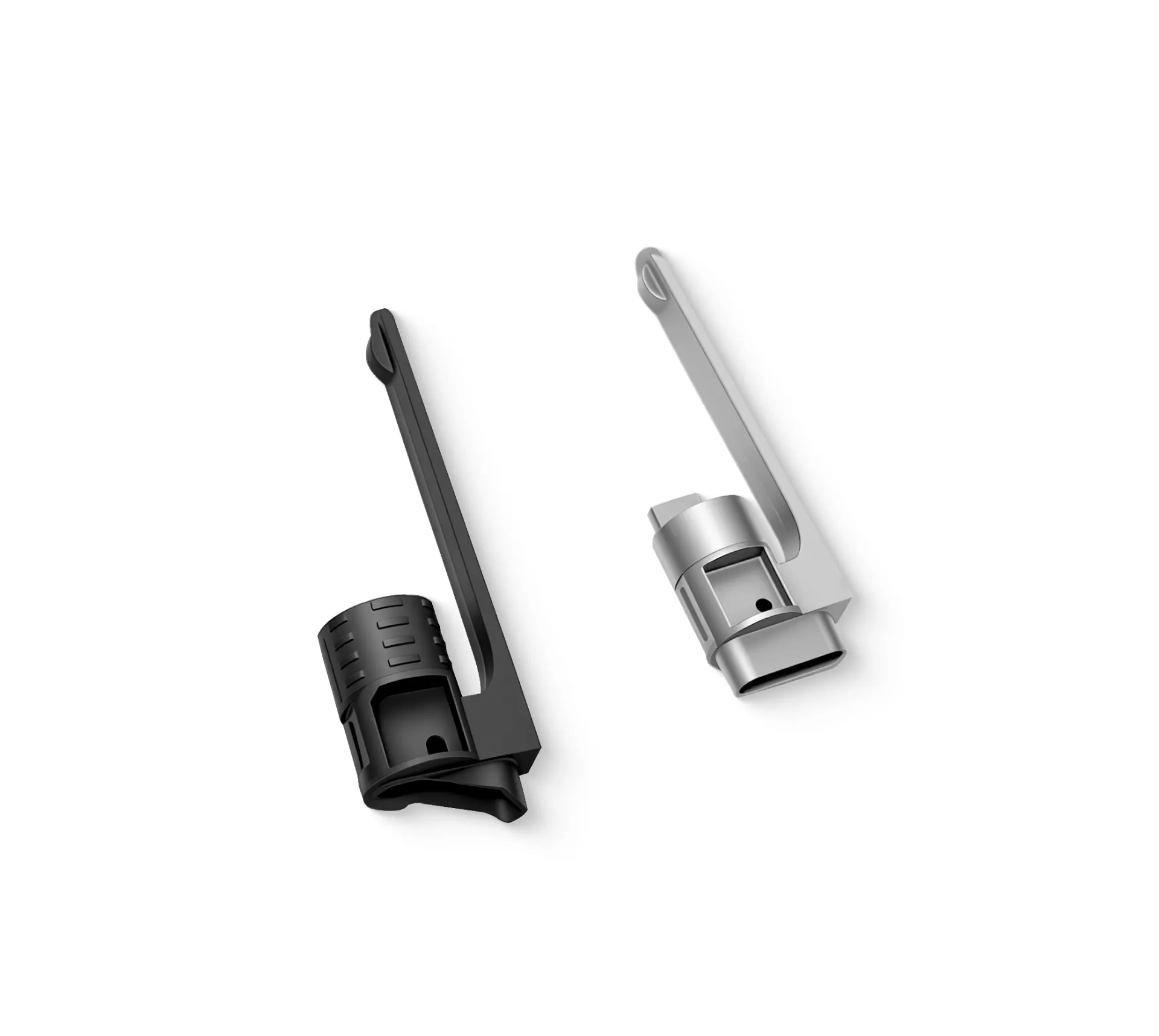
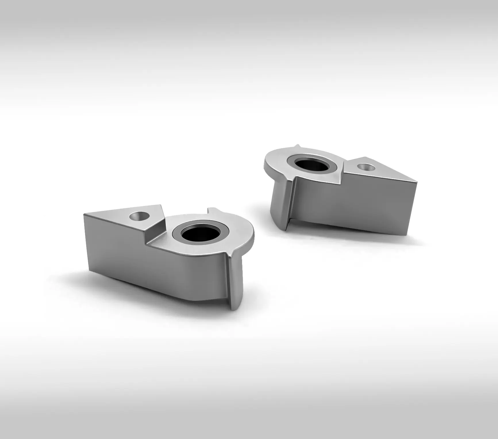
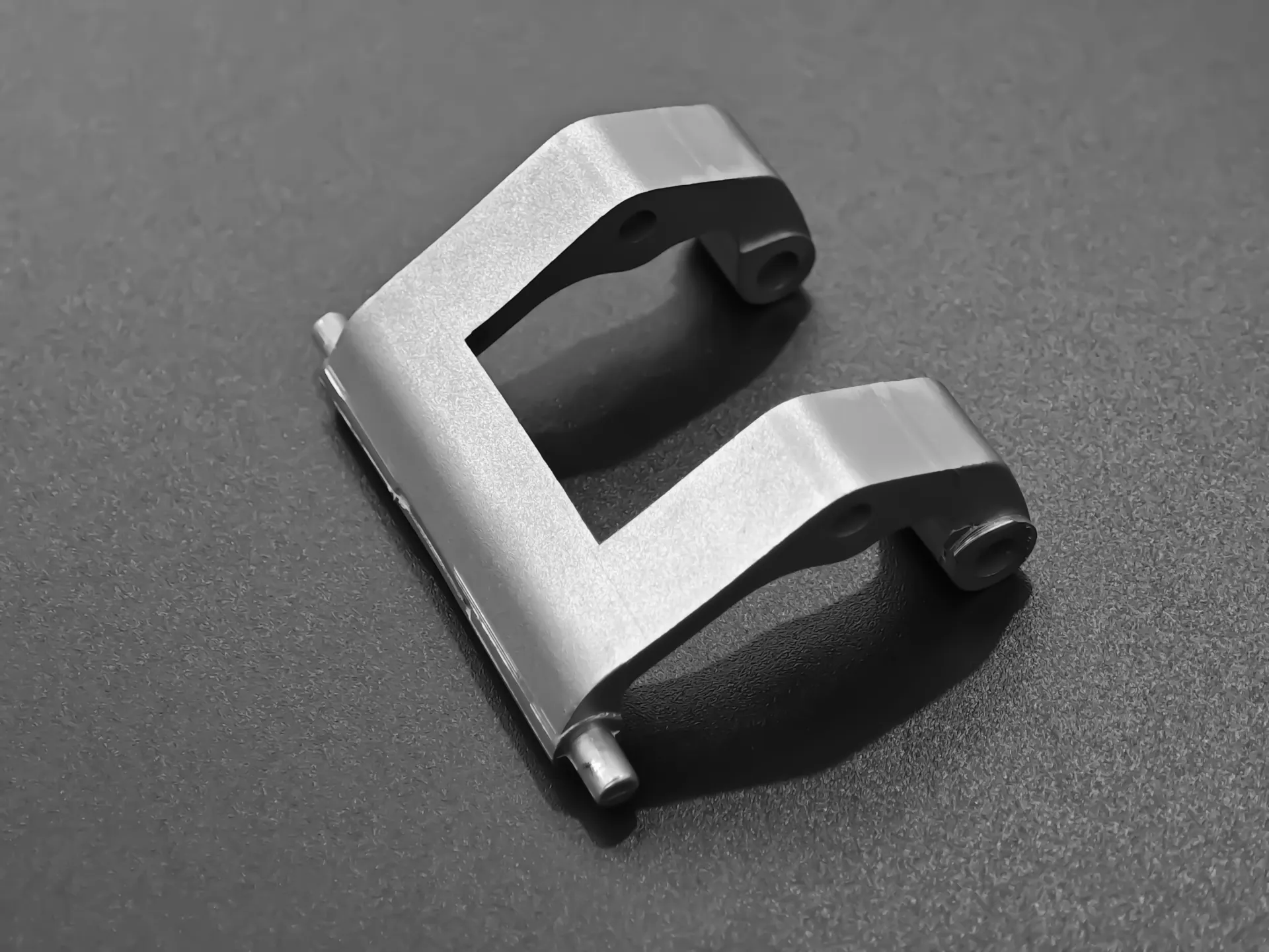
Modern vehicles rely on dozens of precise sensors—from ADAS radar and LiDAR units to engine oil pressure and EV battery thermal management sensors. However, standard machining or die casting often falls short when producing lightweight, highly intricate, and leak-proof enclosures at high volumes.
Machining creates material waste and high unit costs, while standard casting lacks the tight tolerances and material density required to protect delicate chips in high-vibration, corrosive automotive environments. Metal Injection Molding (MIM) solves this issue by combining the design flexibility of plastic injection molding with the structural strength of stainless steel and special alloys.
Below is a detailed guide to designing, evaluating, and sourcing high-performance MIM automotive sensor housings.
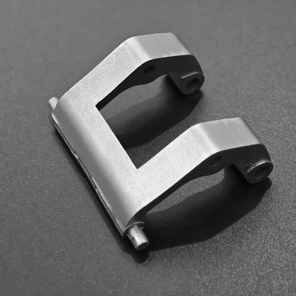
What Are MIM Automotive Sensor Housings?
Metal Injection Molding (MIM) is a powder metallurgy process that blends fine metal powders with a binder material to create a "feedstock." This feedstock is injected into a mold, the binder is removed (debinding), and the component is sintered at high temperatures to achieve up to 96%–99% theoretical density.
For automotive applications, a sensor housing (or enclosure) acts as the protective outer shell for sensitive electronic control units (ECUs), Hall-effect sensors, pressure transducers, and optical sensors.
Metal Powder + Binder ──> Injection Molding ──> Debinding ──> Sintering ──> Finished Housing
Key Technical Specifications
Density: 7.5 - 7.9 g/cm³ (approaching wrought metal)
Standard Tolerances: ±0.3% to ±0.5% of nominal dimensions (down to ±0.02 mm with sizing/coining)
Surface Roughness: Ra 0.8μm - 1.6 μm(as-sintered)
Common Materials: 17-4PH Stainless Steel, 316L Stainless Steel, FN0205 (Fe-Ni alloy), Kovar (for hermetic sealing)
Top Benefits of Using MIM for Automotive Sensor Housings
1. Complex Geometry Without Secondary Machining
MIM enables thin walls, internal threads, complex sealing grooves (O-ring channels), multi-cavity features, and integrated mounting brackets in a single molding step.
2. Superior Material Performance
Sensors mounted near engines, exhaust systems, or underbodies face extreme thermal cycling (-40℃to+150℃+) and corrosive road salts. MIM alloys like 17-4PH deliver tensile strengths exceeding 1000 MPa alongside high corrosion resistance.
3. Cost Efficiency at Scale
For annual volumes exceeding 10,000 to 50,000 units, MIM drastically cuts unit costs by reducing material waste to under 2% and eliminating multi-axis CNC machining steps.
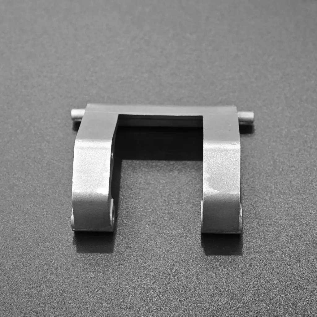
Comparison: MIM vs. CNC Machining vs. Die Casting
| Criteria | MIM (Metal Injection Molding) | CNC Machining | Die Casting (Aluminum/Zinc) |
| Design Complexity | Extremely High (3D shapes, thin walls) | Moderate (limited by tool access) | Moderate-High |
| Material Density & Strength | High (96–99%, high-strength alloys) | Highest (100% wrought) | Lower (porosity risks) |
| Material Yield | >98%(runner recycled) | Low (10–40% material utilization) | High |
| Unit Cost at High Volume | Low | High | Low |
| Initial Tooling Cost | Moderate-High | Low (No tooling) | High |
| Hermetic Sealing Capability | Excellent | Excellent | Fair to Poor (due to voiding) |
Step-by-Step Design & Manufacturing Considerations
Step 1: Optimize Wall Thickness & Radii
Uniformity: Design for consistent wall thickness (ideally 1.0 mm to 3.0 mm) to prevent warping during sintering.
Draft Angles: While MIM requires less draft than die casting, a 0.5° to 1° draft ensures smoother ejector pin operation.
Fillets: Radius all internal edges (≥ 0.5 mm) to avoid stress concentrators during debinding.
Step 2: Select the Right Alloy
17-4PH Stainless Steel: Best for high structural strength and abrasion resistance (e.g., transmission sensors, brake wear sensors).
316L Stainless Steel: Exceptional corrosion resistance and magnetic neutrality (e.g., exhaust gas sensors, exterior ADAS radar housings).
Low Alloy Steels (e.g., 4605 / FN0205): Cost-effective choice when post-plating (nickel/zinc) is acceptable and maximum corrosion resistance isn't required.
Step 3: Plan for Shrinkage (Sintering Stage)
MIM parts shrink 15% to 22% linearly during sintering as the binder burns off and metal particles fuse. Modern mold tool designers use advanced simulation software to calculate exact cavity sizing to hit final ISO tolerances.
Step 4: Secondary Operations (If Required)
Sizing/Coining: Restrikes the part post-sintering for tight tolerances (±0.01mm).
Thread Tapping: While external threads can be molded, high-precision internal threads often undergo quick secondary tapping.
Surface Plating: Electroless Nickel Plating (ENP) or passivating to pass 500+ hour salt-spray tests.
Common Pitfalls & How to Avoid Them
Pitfall 1: Designing Sharp Internal Corners
Risk: Causes cracking during the debinding and sintering phase due to thermal stress concentrations.
Fix: Add generous radii to all internal intersections.
Pitfall 2: Over-specifying Unnecessary Tolerances
Risk: Requesting ±0.005mm across non-critical dimensions forces unnecessary post-machining, driving up costs by 200%.
Fix: Apply tight tolerances only to chip-mating surfaces and O-ring sealing faces; allow standard MIM tolerances (± 0.3%) elsewhere.
Pitfall 3: Ignoring Parting Lines and Gate Marks
Risk: A gate mark on an O-ring sealing face causes fluid leaks under pressure.
Fix: Coordinate with your MIM vendor early to place injection gates on non-critical exterior surfaces.
Frequently Asked Questions (FAQ)
Q1: What is the minimum order quantity (MOQ) for MIM automotive sensor housings?
Because MIM requires custom hardened steel tooling, it is most cost-effective for annual production volumes of 10,000 units or more. For low-volume prototype stages, metal 3D printing (Binder Jetting) can be used before cutting steel molds.
Q2: Can MIM sensor housings achieve leak-proof / hermetic sealing?
Yes. Due to high sintering density (> 97%), MIM housings do not suffer from interconnected porosity. When paired with secondary glass-to-metal sealing or precise laser welding, MIM parts readily pass helium leak testing for automotive sensors.
Q3: What is the typical lead time for a custom MIM sensor housing project?
Tooling & Prototype Samples: 4 to 8 weeks.
Sintering Calibration & First Article Inspection (FAI/PPAP): 2 to 4 weeks.
Mass Production: 3 to 5 weeks per batch.
Conclusion
MIM automotive sensor housings represent the ideal synergy of design freedom, mechanical durability, and scalable unit economics for modern automotive platforms. By accounting for uniform wall thickness, alloy selection, and target tolerances early in the CAD design stage, automotive engineers can eliminate costly machining cycles and avoid field failures.
Share on Social: