What is MIM Process? Step-by-Step Metal Injection Molding Guide
By Yizejing
09, 2026
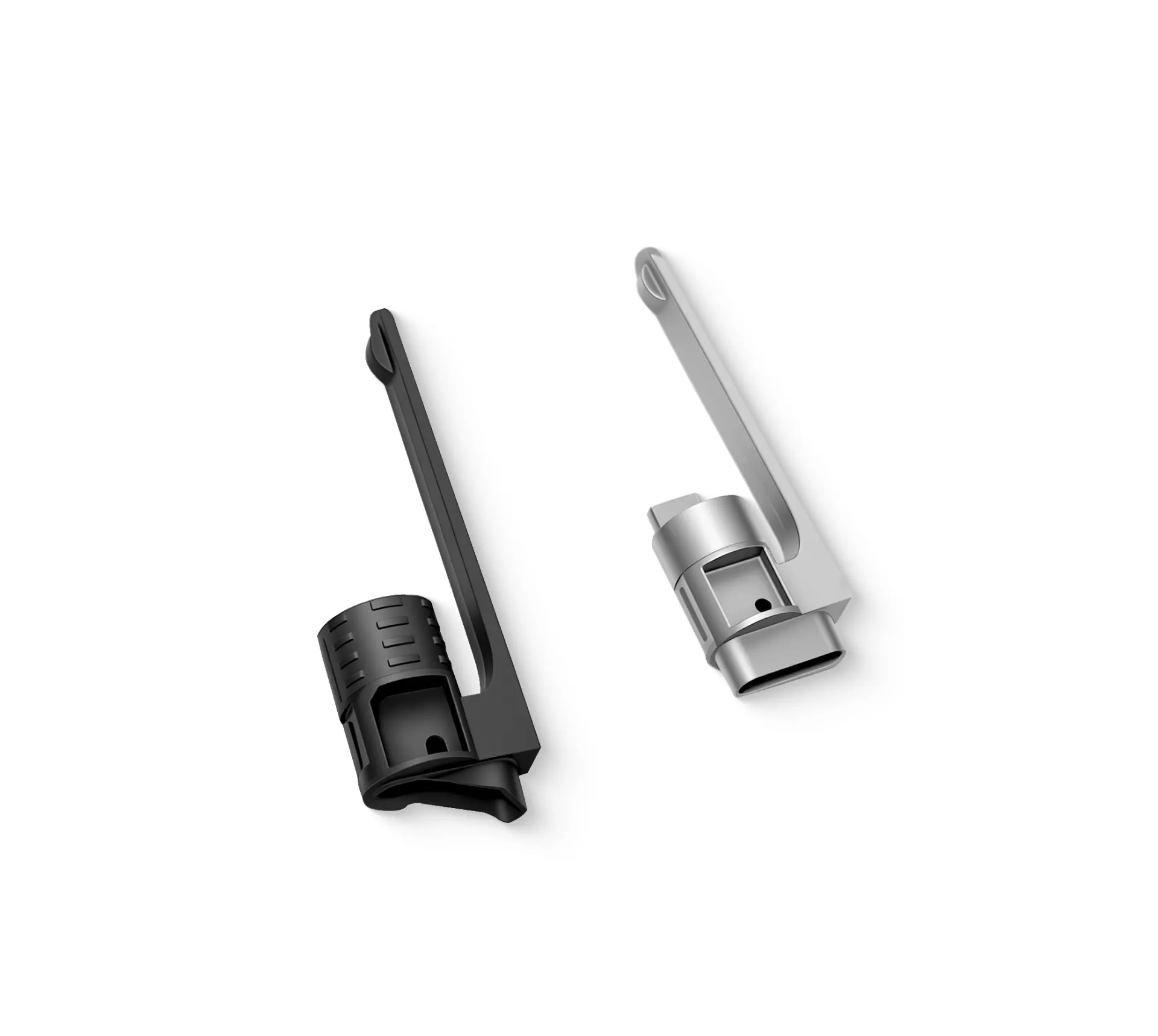
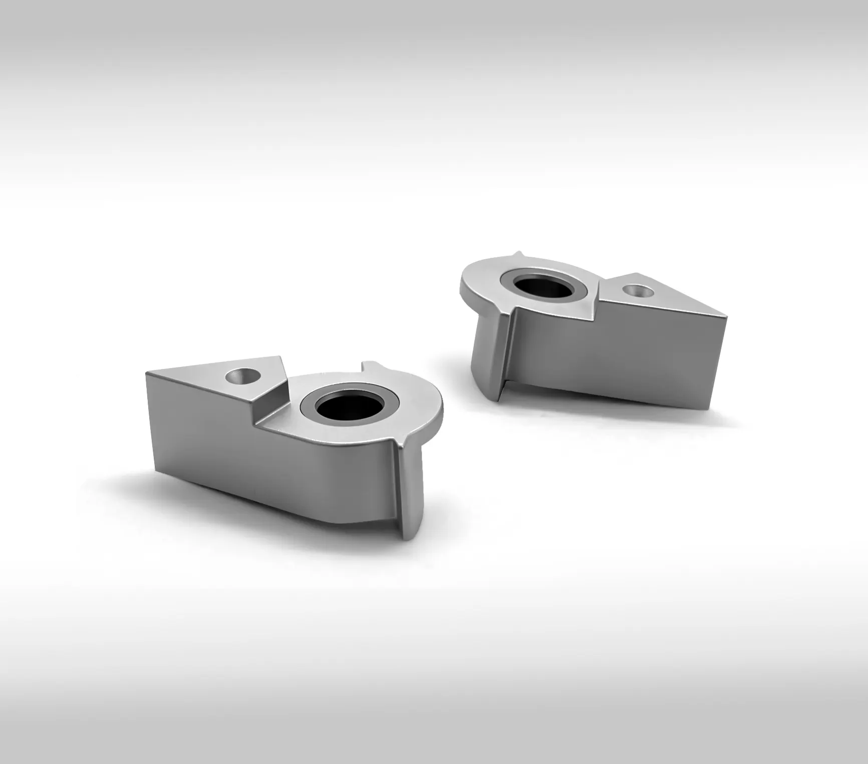
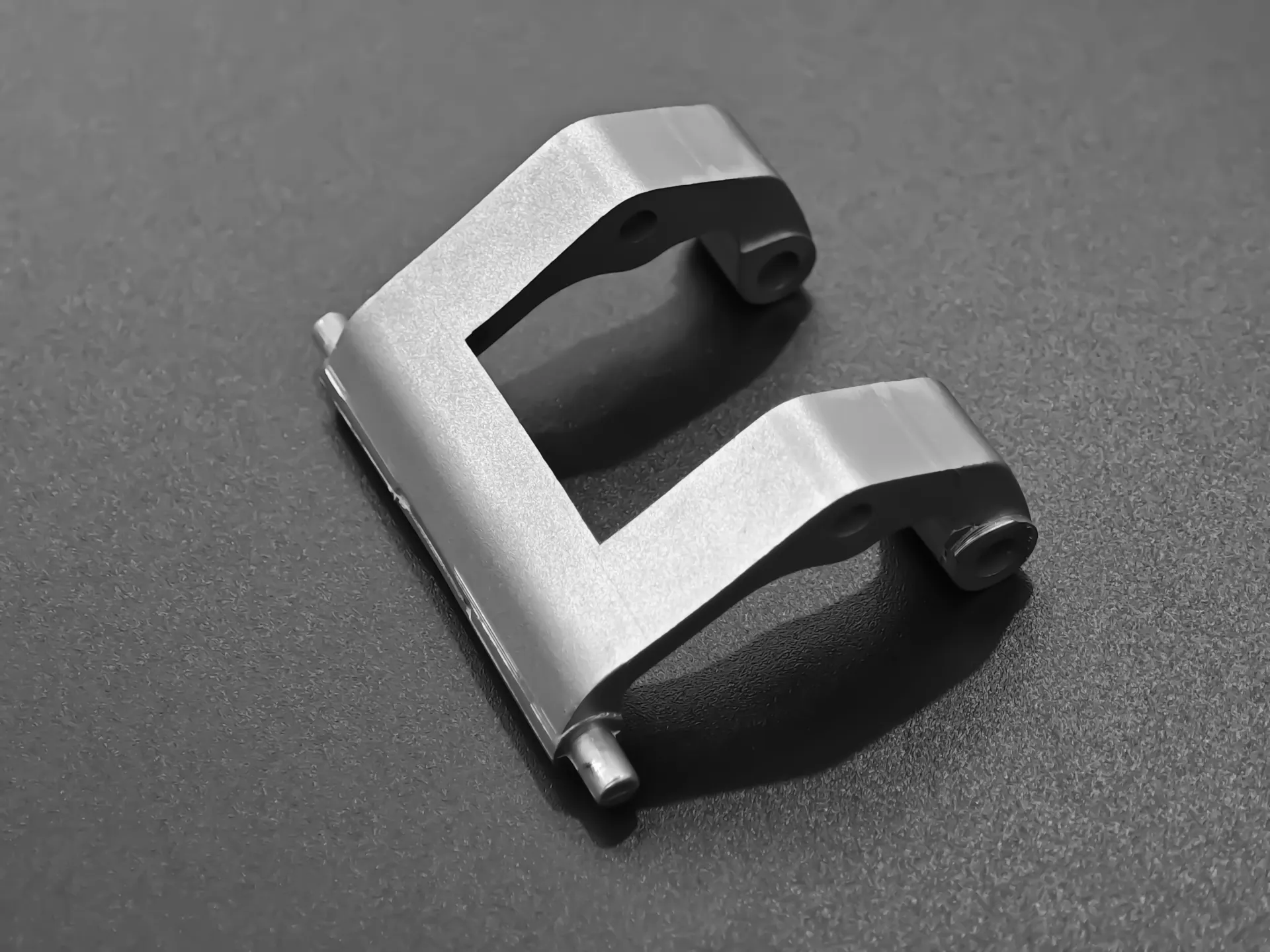
Manufacturing complex, high-precision metal components often leaves engineers facing a tough dilemma: traditional CNC machining incurs skyrocketing costs per part, while investment casting lacks the tight tolerances needed for fine features. If your production volume is scaling into thousands of units and part geometries require thin walls, intricate internal channels, or sharp undercuts, traditional methods quickly hit a wall in cost-efficiency and manufacturability.
Metal Injection Molding (MIM) bridges this gap by combining the design freedom of plastic injection molding with the structural integrity of high-strength metals.
Below is a step-by-step breakdown of what the MIM process is, how each manufacturing stage works, its key engineering advantages, and when you should choose it for your next project.
1. What is the MIM Process?
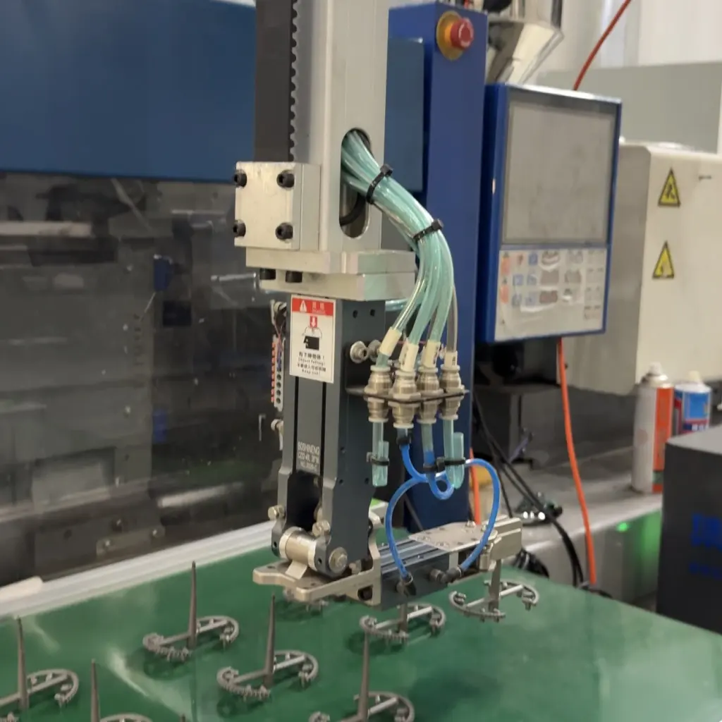
The MIM process (Metal Injection Molding) is a powder metallurgy process that mixes fine metal powders with a polymeric binder material to create a "feedstock." This feedstock is heated and injected into a mold cavity to form complex metal parts in high volumes.
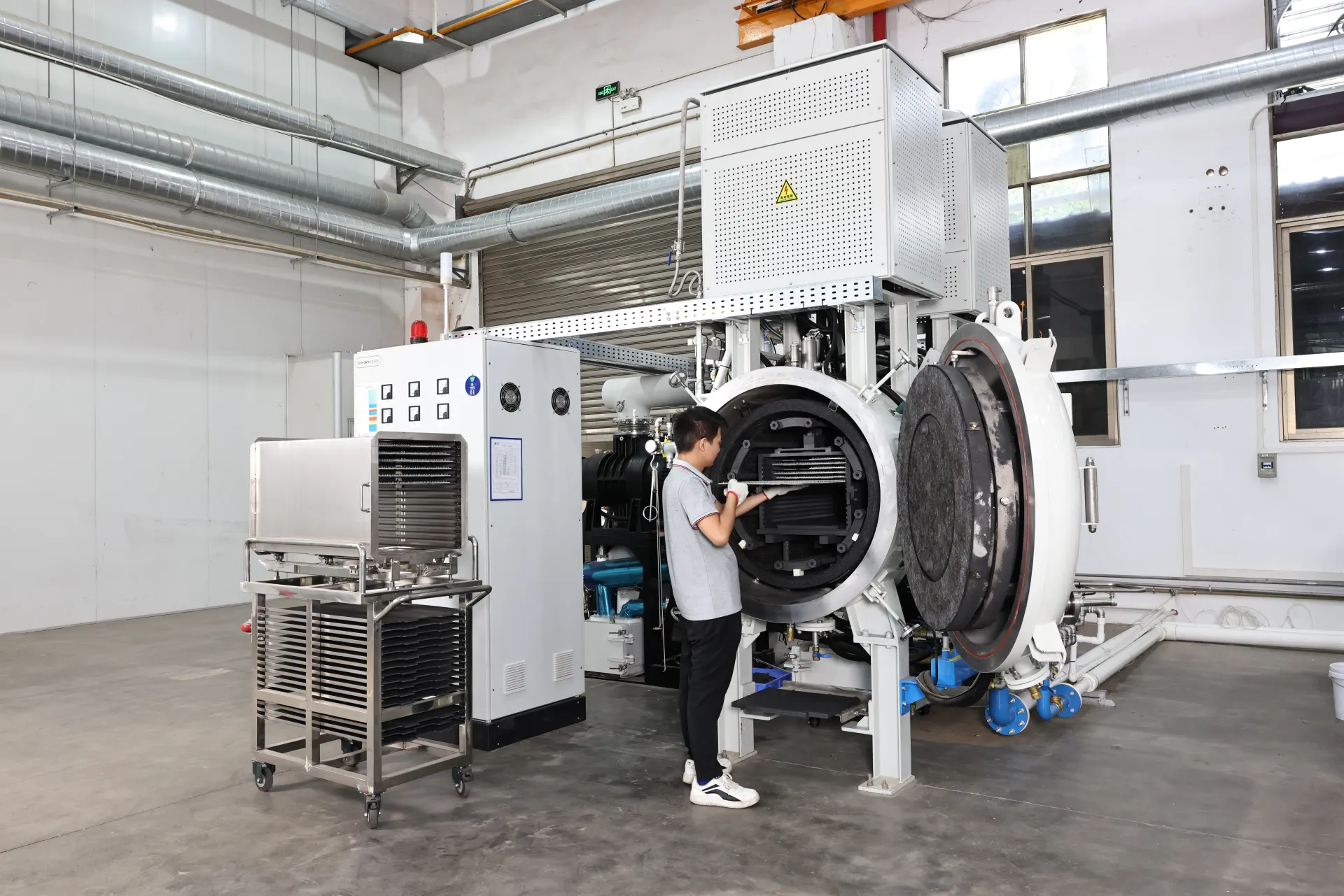
After molding, the binder material is removed during debinding, and the remaining metal structure is densified in a high-temperature vacuum furnace (sintering) to achieve near-wrought physical properties.
Ideal Component Weight: 0.1g to 250g
Typical Wall Thickness: 0.5mm to 10mm
Final Part Density: 95% – 99% of wrought metal
2. The 4 Core Steps of the Metal Injection Molding Process
Executing a successful MIM run relies on four interconnected manufacturing phases. A mistake in early binder formulation can lead to warping or cracking during the final heat treatment.
Step 1: Feedstock Preparation (Compounding)
Ultra-fine metal powders (typically < 20μm) are mixed with a thermoplastic binder system (waxes and polymers) at precise ratios (typically 60% metal powder, 40% binder by volume). The mixture is extruded and granulated into small pellets known as feedstock.
Step 2: Injection Molding (Green Part)
The feedstock pellets are fed into a standard injection molding machine. The melted material flows into a custom mold cavity under heat and pressure. The output is a "Green Part"—dimensionally oversized (usually 15–20% larger than final target dimensions) to account for shrinkage during sintering.
Step 3: Debinding (Brown Part)
The polymeric binder must be removed without disturbing the shape of the metal particles. Debinding is performed using solvent immersion, thermal degradation, or catalytic oxidation (such as nitric acid gas for polyacetal binders). Once the primary binder is extracted, the porous structure is called a "Brown Part."
Step 4: High-Temperature Sintering
The brown parts are loaded into high-vacuum or controlled atmosphere (hydrogen/argon) furnaces. Temperatures are raised close to the metal’s melting point (typically 1200℃-1400℃). The remaining backbone binder volatilizes, and the metal particles fuse together. The component shrinks uniformly down to its final design dimensions while achieving high mechanical strength.
Pro Tip: Post-processing operations—such as HIP (Hot Isostatic Pressing), heat treating, CNC finish machining, or electroplating—can be applied post-sintering if ultra-tight tolerances (<±0.03mm) or custom surface finishes are required.
3. MIM vs. CNC Machining vs. Investment Casting
Selecting the right process depends directly on design complexity, annual volume, and part weight:
| Manufacturing Parameter | MIM Process | CNC Machining | Investment Casting |
| Annual Volume Target | High (> 5,000 pcs) | Low-to-Medium (1 - 1,000pcs) | Medium (500 - 10,000 pcs) |
| Geometric Complexity | Very High (Internal threads, cross-holes) | Medium (Limited by tool paths) | Moderate |
| Material Utilization | > 95% (Near-net shape) | Low (High scrap material) | Medium |
| Tooling Cost | Moderate to High (Initial mold) | None / Minimal Setup | Moderate |
| Unit Cost at Scale | Extremely Low | High | Medium |
4. Key Engineering Benefits & Material Options
Design Freedom & Complex Geometries
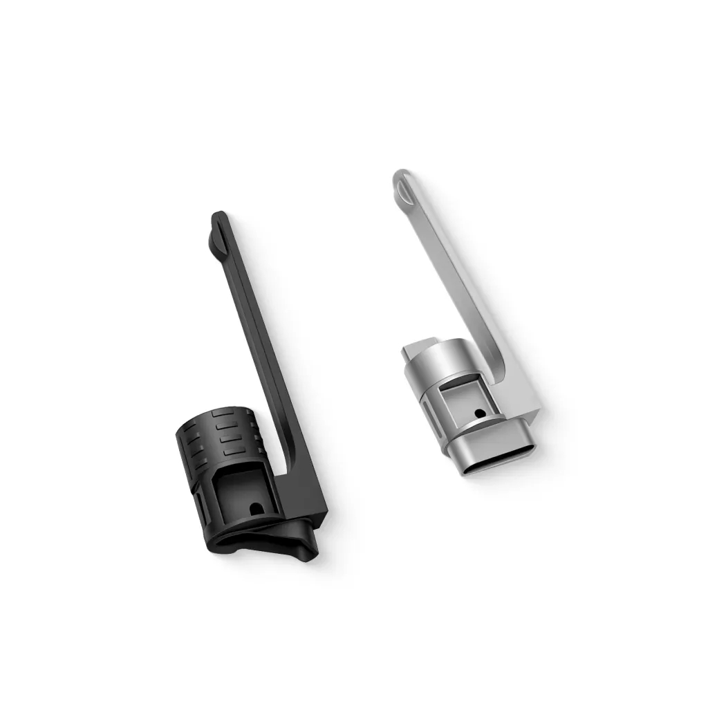
Features like internal threads, knurling, thin-walled ribs, custom logos, and complex undercuts can be integrated into a single mold, eliminating multi-part assemblies and manual alignment.
Versatile Material Compatibility
Virtually any alloy that can be atomized into fine powder can be processed via MIM:
Stainless Steel: 316L (corrosion resistance), 17-4PH (high strength/hardness)
Low Alloy Steels: 4140, 8620, 2200 (structural mechanical parts)
Tool Steels: M2, M4, S7 (wear-resistant components)
Specialty Alloys: Titanium (Ti-6Al-4V), Cobalt-Chrome, Tungsten Heavy Alloys, Kovar
5. Frequently Asked Questions (FAQ)
Q1: How much do parts shrink during the MIM sintering phase?
MIM components typically shrink by 15% to 22% linearly during sintering as the binder voids collapse and metal particles sinter together. Tool design software and mold engineers calculate exact shrinkage rates based on the specific powder-to-binder ratio.
Q2: Is MIM cost-effective for low-volume production?
Generally, no. MIM requires initial investment in custom steel tooling. It is most cost-effective for mid-to-high volume production runs (typically starting at 5,000+ parts per year) where tooling costs are quickly amortized.
Q3: Are MIM parts as strong as fully machined solid metals?
Yes. Modern MIM parts achieve densities between 95% and 99% of theoretical wrought density. Their tensile strength, hardness, fatigue resistance, and magnetic performance match or exceed conventional wrought metal standards.
6. Conclusion & Related Resources
The MIM process is an unbeatable solution for producing small, complex, high-precision metal parts at scale. By combining plastic molding flexibility with metallurgy performance, MIM eliminates scrap waste, reduces assembly steps, and significantly cuts unit production costs.
Share on Social: