



10 Design Guidelines for Metal Injection Molding (MIM) Parts
By hqt
08, 2026
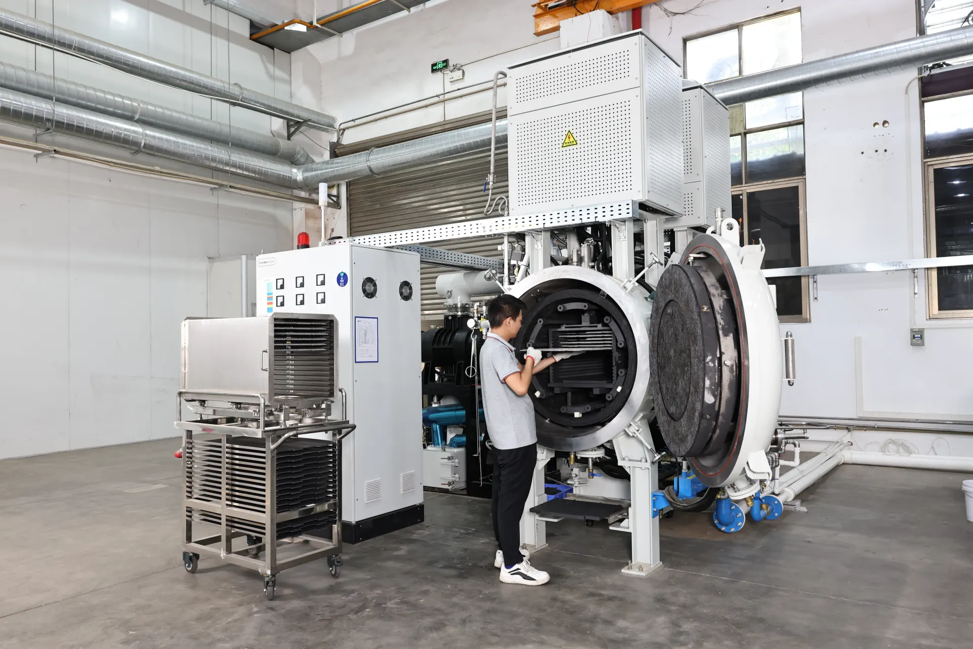
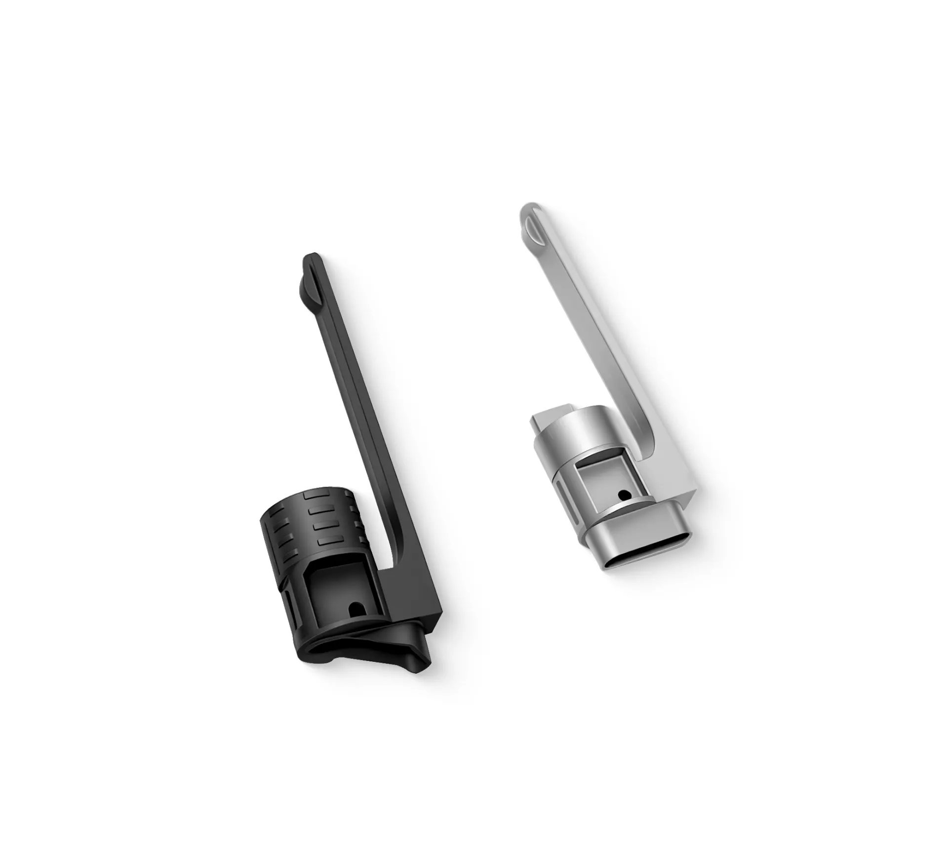
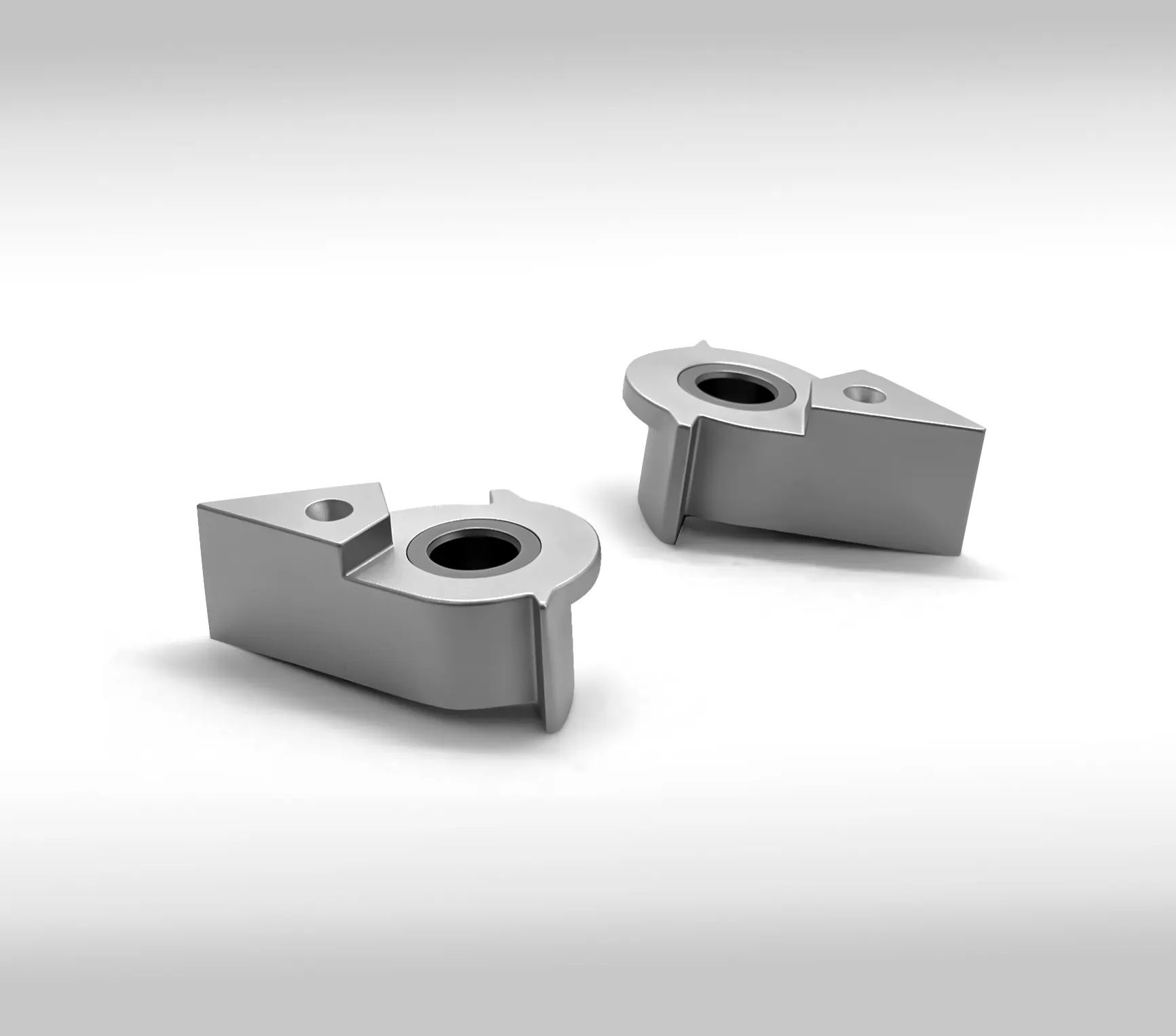
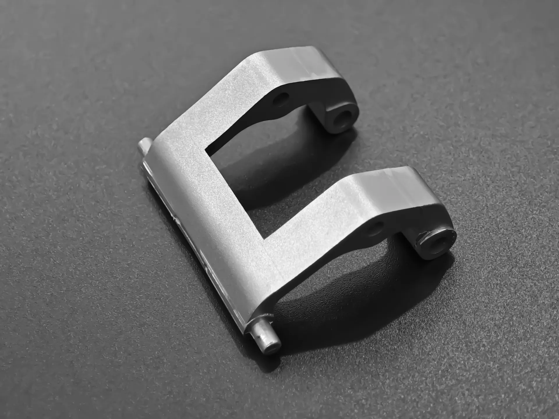
Metal Injection Molding (MIM) is a revolutionary manufacturing process that combines the design freedom of plastic injection molding with the material properties of traditional metallurgy. It allows engineers to produce complex, high-volume, and high-strength metal parts that would be difficult or cost-prohibitive to machine.
However, to unlock the full potential of MIM and avoid costly defects during debinding and sintering, parts must be designed with the process in mind. Below is a practical metal injection molding design guide featuring 10 essential MIM design guidelines to help you optimize your component designs.
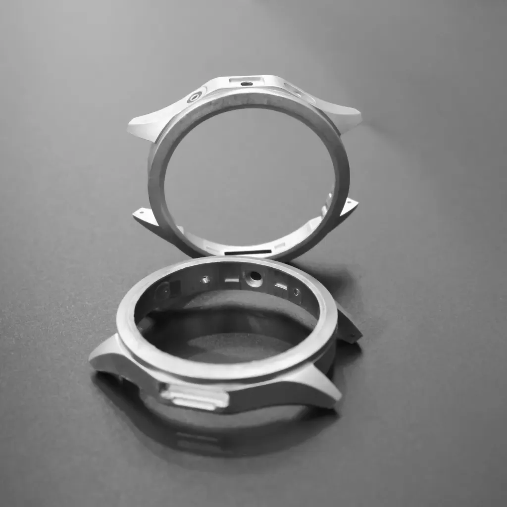
1. Optimize Wall Thickness for Uniformity
Maintaining a consistent wall thickness is the single most critical factor in MIM design。
Recommended Range: Ideally, maintain wall thicknesses between 1.0 mm and 3.0 mm (0.040" to 0.120").
Avoid Thick Sections: Thick cross-sections increase cooling times, create internal voids, and cause severe distortion during sintering.
Design Tip: Use coring, ribbing, or pocketing to hollow out thick areas while maintaining structural integrity.
2. Incorporate Proper Draft Angles
While MIM allows for more intricate detail than conventional powder metallurgy, adding a draft angle is crucial for smooth ejection from the mold.
Recommended Angle: A draft angle of 0.5° to 1.0° per side is generally sufficient.
Why It Matters: Proper draft prevents dragging, surface scuffing, and mold wear during the part removal process.
3. Generous Radii and Fillets (Avoid Sharp Corners)
Sharp internal and external corners act as stress concentrators and lead to cracking during the high-shrinkage sintering phase.
Internal Radii: Provide a minimum internal radius of 0.5 mm (0.020").
Benefits: Smooth radii improve feedstock flow during injection, reduce tool wear, and enhance the overall fatigue strength of the final metal component.
4. Account for Sintering Shrinkage Compensation
During the thermal debinding and sintering stage, the binder material burns off, and the metal powder densifies. This causes significant volume reduction.
Shrinkage Rate: MIM parts shrink by 15% to 20% linear dimensionally during sintering.
Shrinkage Compensation: Tooling engineers scale up the mold cavity size using precise shrinkage compensation factors calculated for the specific alloy powder and binder mix. Designers should ensure uniform wall sections to allow predictable, isotropic (even) shrinkage.
5. Set Realistic Tolerances
MIM delivers exceptional repeatability, but understanding realistic tolerance limits avoids unnecessary post-processing costs.
Standard Tolerances: As-sintered MIM parts typically achieve ±0.3% to ±0.5% of nominal dimensions (or ±0.05 mm / ±0.002" for small features).
Tight Tolerances: Features requiring tighter tolerances (e.g., ±0.01 mm) should be designated for secondary operations like CNC machining, grinding, or coining.
6. Design Flat Supporting Features for Sintering
During the high-temperature sintering phase, MIM parts soften before reaching full density. Without proper support, parts can sag or warp.
Design Tip: Incorporate flat, coplanar surfaces into the geometry to allow the part to rest securely on flat ceramic sintering trays (setters) without requiring custom, expensive support fixtures.
7. Strategic Placement of Gates and Parting Lines
The gate is where the molten feedstock enters the mold cavity. Its location directly impacts part aesthetics and structural performance.
Gate Location: Position gates on non-critical, thicker cross-sections. Avoid placing gates on high-stress areas or precision mating surfaces, as gate vestige (residue) will remain after trimming.
Parting Line: Keep parting lines on flat planes or natural corners to minimize visible seam lines on finished parts.
8. Smart Use of Ribs and Gussets
To maintain strength without increasing wall thickness, use ribs and gussets.
Rib Geometry: Rib thickness should generally be 50% to 75% of the adjoining wall thickness to prevent sink marks on the outer surface.
Benefits: Ribs enhance rigidity, improve material flow, and facilitate uniform cooling.
9. Design Feasible Threads and Undercuts
MIM allows internal and external threads as well as undercuts to be molded directly into the part, eliminating secondary machining.
Threads: External threads are straightforward to mold along the parting line. Internal threads are possible using unscrewing molds or collapsible cores, though coarse threads are preferred over ultra-fine threads.
Undercuts: External undercuts require side-action slides. Keep undercuts simple to minimize tool complexity and maintenance.
10. Maximize Feature Integration
One of MIM's greatest financial advantages is part consolidation—combining multiple components (e.g., pins, brackets, gears) into a single molded metal part.
Consolidation: Evaluate your assembly to see if multi-piece assemblies can be merged into a single MIM component, reducing assembly labor, inventory costs, and potential failure points.
Summary Matrix: MIM Quick Design Checklist
| Design Feature | Recommended MIM Parameter |
| Wall Thickness | 1.0 mm – 3.0 mm (Uniform throughout) |
| Draft Angle | 0.5° – 1.0° |
| Fillet Radius | Minimum 0.5 mm (0.020") |
| Standard Tolerance | ±0.3% – ±0.5% of dimension |
| Linear Shrinkage | 15% – 20% (Accounted for in tool scale) |
Need Help Optimizing Your MIM Design?
Following these MIM design guidelines early in your product development phase ensures smoother prototyping, faster cycle times, and lower production costs.
If you are currently developing a metal component, contact our engineering team today for a free DFM (Design for Manufacturability) review!Contact Information:Email: Yuliya.chen@yizemould.com Telephone/WhatsApp: +86 13342659272
Share on Social: