



Common Defects in Metal Injection Molding (MIM) and How to Prevent Them: An R&D Guide
By Yizejing
08, 2026
Metal Injection Molding (MIM) offers unmatched freedom for designing complex, high-precision metal parts in high volumes. However, for R&D engineers and technical teams, transitioning a component from a CAD model to a fully sintered metal part can present unique manufacturing challenges.
Because MIM involves a four-stage process—molding, debinding, sintering, and optional secondary operations—defects can originate at any step and manifest downstream. Implementing robust MIM quality control early in the development phase is essential to prevent costly re-tooling and production delays.
Here is an engineering breakdown of the most common MIM defects, their root causes, and actionable strategies to prevent them during design and processing.
1. Cracking (Green, Brown, and Sintered Stage)
Cracking is one of the most frustrating defect types because it can occur at any stage of the process—as a "green" molded part, a "brown" debound part, or a final sintered component.
Root Causes:
Thermal & Mechanical Shock: Rapid cooling in the mold or aggressive thermal ramp-up rates during debinding.
Stress Concentration: Sharp internal corners (R<0.5mm) acting as stress raisers.
Ejection Stress: Improper ejection pin placement or high demolding friction damaging fragile green parts.
How to Prevent It:
Apply Generous Fillets: Ensure a minimum radius of 0.5 mm on all internal edges to distribute thermal stresses evenly.
Optimize Thermal Cycles: Implement gradual heating profiles during solvent/thermal debinding to prevent binder pressure buildup inside the part.
Refine Tool Ejection: Use uniform ejector pin force and optimize mold release drafts ($0.5^\circ - 1.0^\circ$).
2. Warpage and Distortion
Warpage occurs when a part loses its intended geometry, bending or twisting during processing—most frequently during high-temperature sintering when the metal powder densifies and shrinks by 15% to 20%.
Root Causes:
Non-Uniform Wall Thickness: Differential cooling speeds cause uneven shrinkage forces across the component.
Inadequate Support During Sintering: As the binder drains and metal powders fuse, gravity causes unsupported overhangs to sag.
Feedstock Segregation: An inconsistent mix of powder and binder leading to uneven shrinkage rates.
How to Prevent It:
Maintain Uniform Cross-Sections: Design consistent wall thicknesses (ideally 1.0 mm to 3.0 mm) or use cored-out sections with ribs.
Utilize Custom Sintering Setters: Design parts with flat baseline reference features, or use custom ceramic setter trays to support complex geometries during firing.
Homogeneous Feedstock Control: Enforce strict feedstock mixing standards to guarantee consistent powder-to-binder volume ratios.
3. Dimensional Variation
Out-of-tolerance dimensions undermine assembly functionality and are a primary reason for part rejection during quality inspection.
Root Causes:
Inconsistent Sintering Temperatures: Temperature fluctuations within the sintering furnace cause localized variations in shrinkage.
Feedstock Density Variations: Variations in powder loading from batch to batch alter the total linear shrinkage percentage.
Tool Wear & Mold Temperature Shifts: Unstable cavity temperatures during injection molding lead to inconsistent green part weights.
How to Prevent It:
Rigorous In-Process Control (IPC): Weigh green parts immediately after molding. Green part weight consistency (typically within ±0.2% ) directly correlates with final dimensional accuracy.
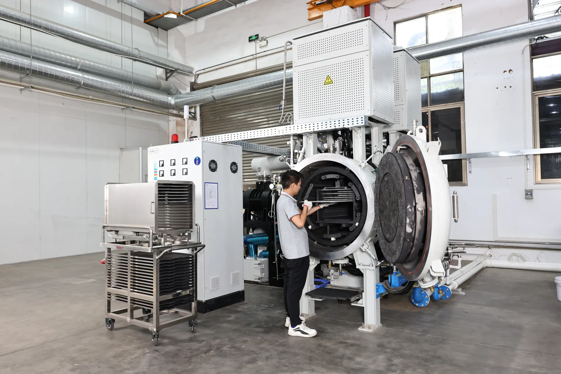
Precision Thermal Profiling: Use multi-zone controlled sintering furnaces with continuous atmosphere monitoring to ensure temperature uniformity across all setter trays.
Secondary Coining or Machining: For ultra-tight tolerance features (tighter than±0.3%), design the workflow to include a secondary sizing/coining or CNC finish pass.
4. Density Problems (Porosity and Voids)
Achieving target density (typically > 95% to 98% of theoretical metal density) is critical for mechanical performance, corrosion resistance, and post-process plating or heat treatment.
Root Causes:
Incomplete Sintering: Insufficient hold time or temperature during sintering leaves microscopic interconnected porosity.
Air Entrapment / Sink Marks: Trapped air during high-velocity injection or localized shrinkage voids in excessively thick sections.
Incomplete Debinding: Residual binder trapped inside the part decomposes violently during sintering, creating internal voids or blistering.
How to Prevent It:
Optimize Sintering Profiles: Fine-tune peak sintering temperatures and dwell times according to the specific alloy (e.g., 316L, 17-4PH, or Fe-Ni steels).
Coring Thick Sections: Avoid solid sections thicker than 4.0 mm to eliminate void formation and ensure full debinding gas evacuation.
Controlled Molding Parameters: Optimize hold pressure and injection speeds to ensure complete mold filling without trapping volatiles.
Technical Summary: MIM Quality Control Checklist for R&D
| Defect Type | Primary Cause | R&D / Design Mitigation | Process Control Solution |
| Cracking | Stress concentrations / Ejection force | Add fillets (≥0.5mm); uniform draft | Slow debinding thermal ramp; balanced ejector pins |
| Warpage | Non-uniform shrinkage / Gravity sag | Design uniform walls; add flat ceramic support planes | Custom sintering setters; homogeneous feedstock |
| Dimensional Variation | Shrinkage inconsistency / Thermal drift | Allow ±0.3% - 0.5%standard tolerances | Strict green weight monitoring (±0.2target) |
| Density Issues | Incomplete debinding or sintering | Avoid walls > 4.0mm; core out thick blocks | Optimized atmosphere control and sintering soak time |
Partner with MIM Engineering Experts Early
Defect prevention in Metal Injection Molding starts long before the feedstock reaches the mold. By applying robust Design for Manufacturability (DFM) principles during the initial R&D phase, engineers can eliminate potential defects while protecting budget and timeline requirements.
Developing a complex metal component? Submit your CAD files to our engineering team today for a comprehensive MIM DFM Analysis and Defect Risk Assessment!Contact Information:Email: Yuliya.chen@yizemould.com Telephone/WhatsApp: +86 13342659272
Share on Social: