Ultimate Guide to Metal Molding: MIM Process, Design Rules, and Cost Reduction Strategies
By Yizejing
09, 2026
Are you struggling to manufacture highly complex, small metal parts without incurring sky-high machining costs? Traditional CNC machining often wastes up to 70% of raw material when producing intricate structural components, while traditional casting methods frequently fail to achieve the required micro-tolerances. This dilemma leaves engineering and procurement teams stuck between bloated unit costs and delayed production schedules.
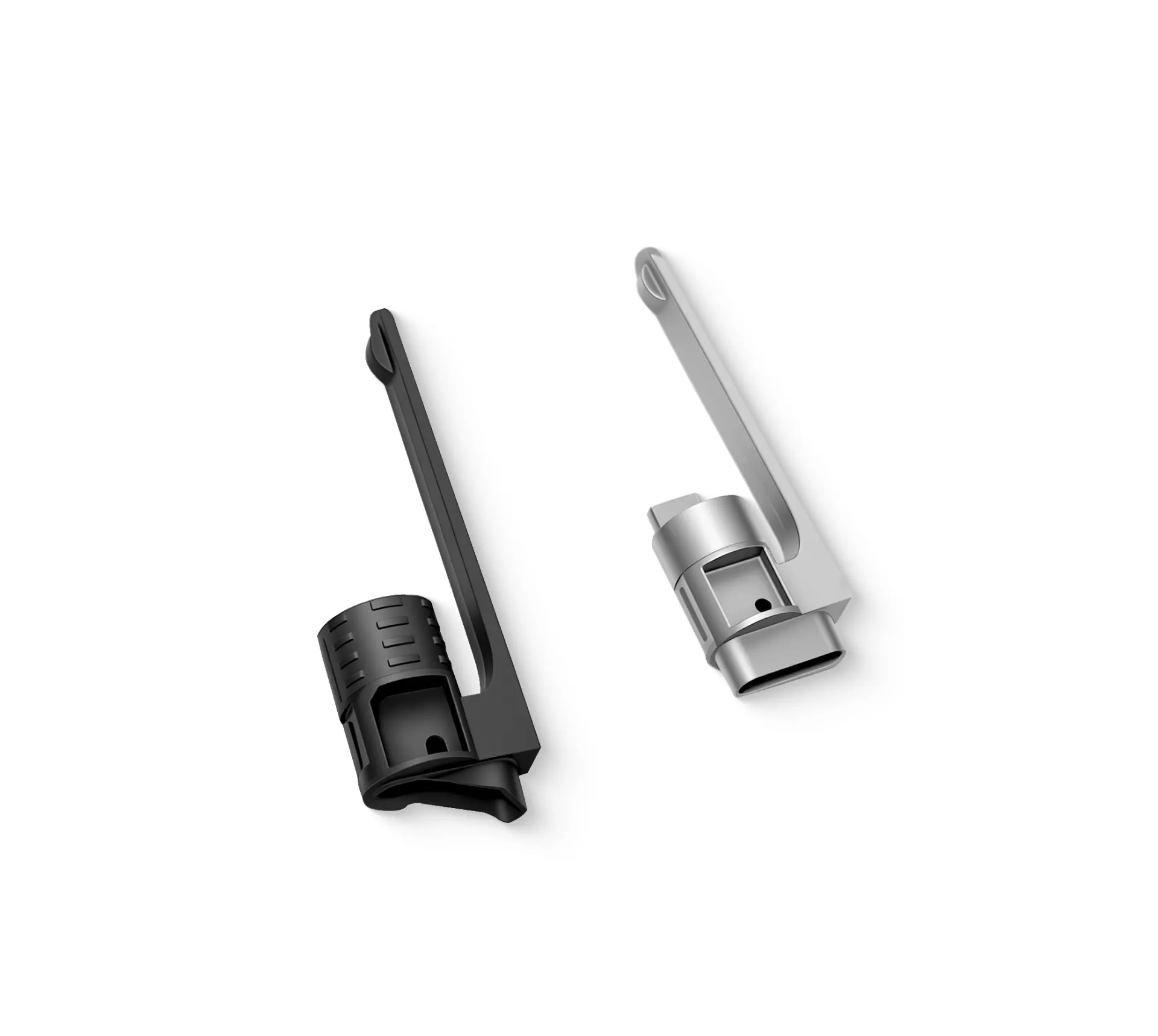
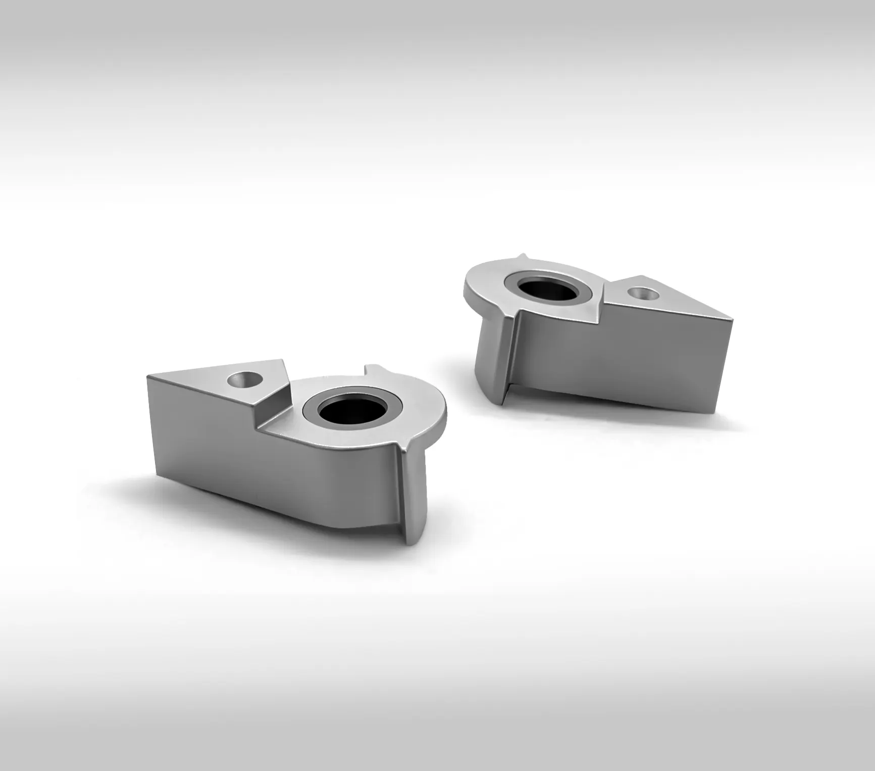
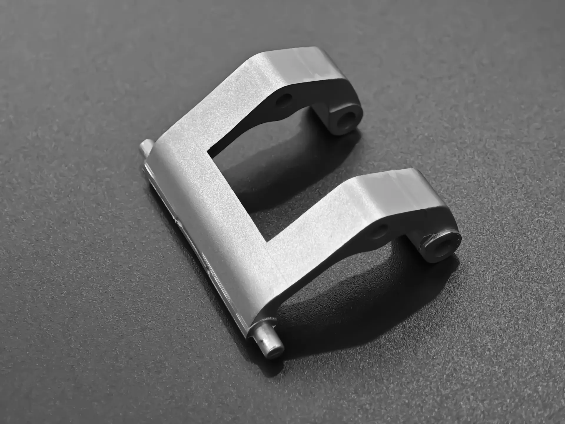
Metal molding—specifically Metal Injection Molding (MIM)—eliminates this tradeoff. Combining the geometric design freedom of plastic injection molding with the structural strength of solid metal, this process enables the mass production of net-shape precision metal parts. In this comprehensive guide, we unpack the complete metal molding process, key design guidelines, material selection strategies, and proven cost-reduction techniques to help you make informed engineering decisions.
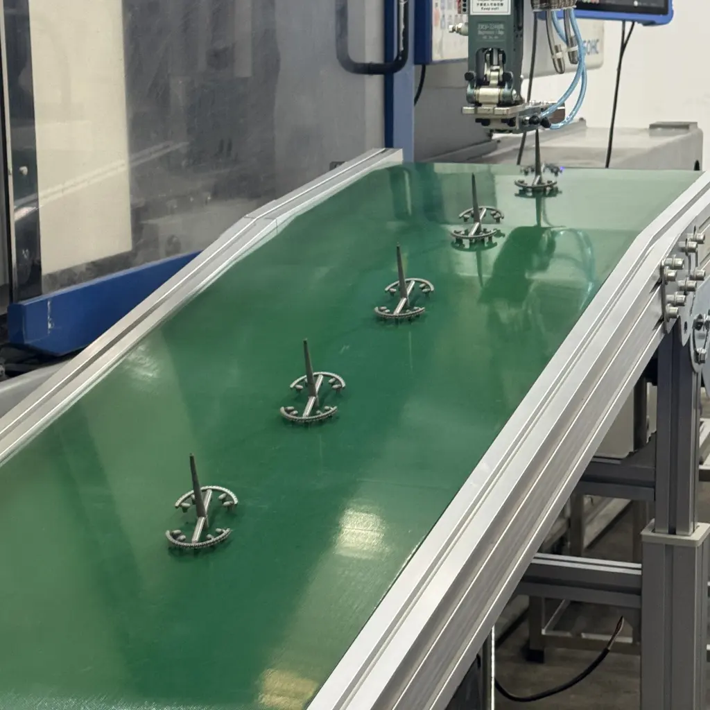
1. Understanding Metal Molding: MIM vs. Alternative Methods
To choose the optimal manufacturing route for your precision components, compare how Metal Injection Molding stacks up against traditional processes across critical manufacturing parameters.
| Metric / Parameter | Metal Injection Molding (MIM) | Die Casting | Metal Stamping | CNC Machining |
| Part Complexity | Very High (3D shapes, threads) | Moderate to High | Low to Moderate (2.5D) | High |
| Material Utilization | 95% – 98% | 85% – 90% | 50% – 70% | 15% – 40% |
| Dimensional Tolerance | ±0.3% to ±0.5% | ±0.5% | ±0.1 mm | ±0.01 mm |
| Ideal Part Weight | < 250 g (Optimal: 0.2g–50g) | 50g – 5kg+ | < 500g | Any weight |
| Initial Tooling Cost | Moderate to High | High | Moderate to High | None |
| Unit Cost (High Volume) | Very Low | Low | Very Low | High |
2. Step-by-Step Breakdown of the MIM Metal Molding Process
The Metal Injection Molding (MIM) process transforms fine metal powder into dense, strong metal components through four distinct operational steps.
1.Feedstock Preparation:Mixing metal powder with polymeric binders。
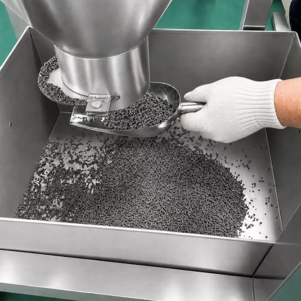
Ultra-fine metal powders (typically smaller than 20 microns) are homogeneously mixed with a custom thermoplastic binder system (usually 60% powder and 40% binder by volume). The mixture is heated and granulated into uniform pellets known as feedstock.
2.Injection Molding:Forming the 'Green Part'。
The feedstock pellets are fed into a standard injection molding machine, melted, and injected into a mold cavity under high pressure. The cooled, ejectable part is called a Green Part. It is roughly 15% to 20% larger than the final intended dimension to account for shrinkage in later steps.
3.Debinding:Removing the primary binder material。
The Green Part undergoes a catalytic, solvent, or thermal debinding process to leach out the primary binder phase while leaving a minor secondary binder intact to maintain structural integrity. The resulting porous component is called a Brown Part.
4.Sintering:Achieving up to 99% theoretical density。
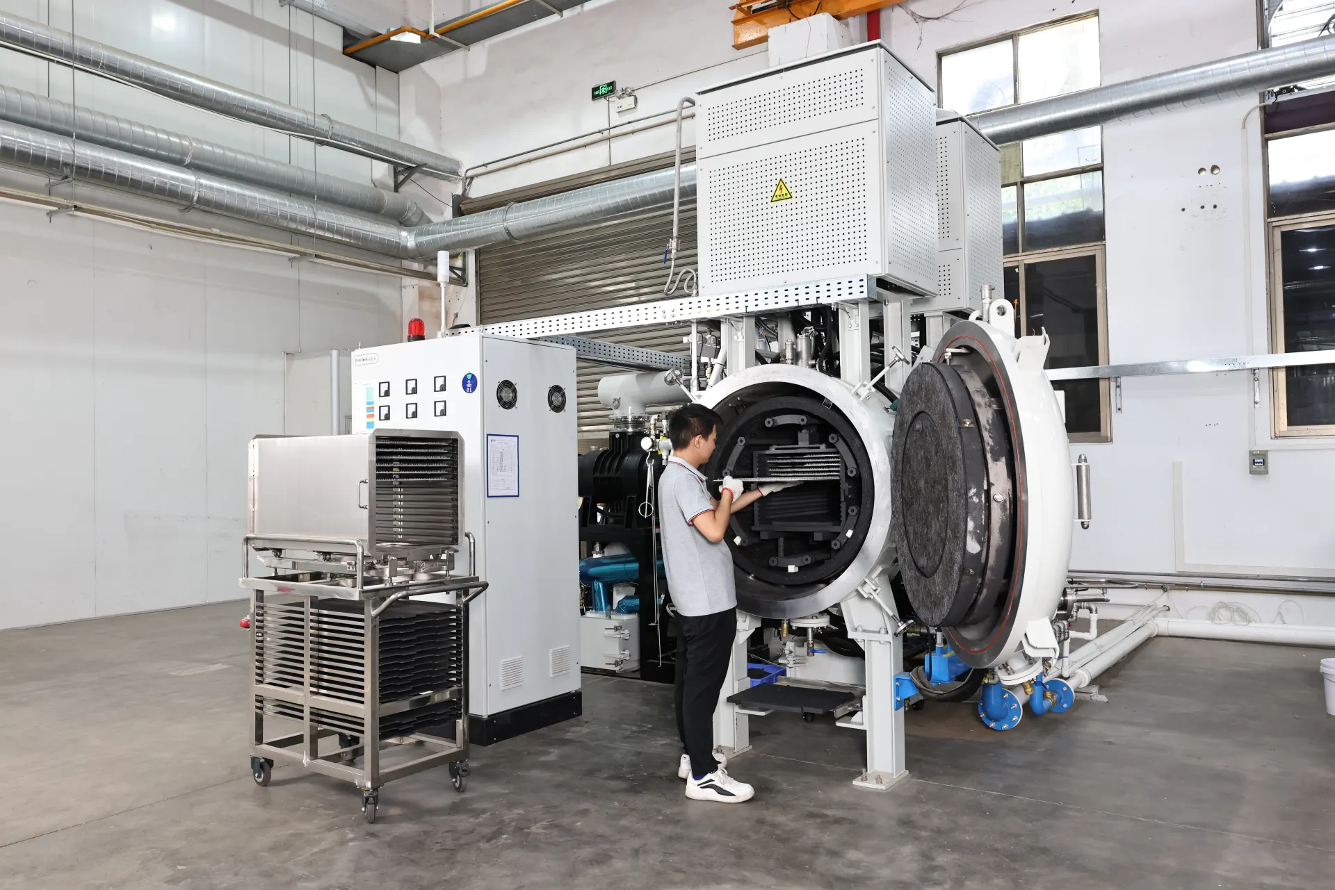
The Brown Parts are loaded into a high-temperature atmosphere or vacuum furnace. Heated near the metal's melting point (1,200°C to 1,400°C), the remaining binder burns off, and the metal particles fuse together via atomic diffusion. The part shrinks predictably to its final dimensions, reaching 96%–99% theoretical density.
3. Essential Engineering Design Rules for Metal Molding
To optimize metal molding manufacturability and prevent defects like warping, internal voids, or cracking during sintering, follow these design rules:
Uniform Wall Thickness
Target range: Keep wall thickness between 1.0 mm and 3.0 mm.
Risk of non-uniformity: Thick sections cause sink marks and internal voids, while thin sections may underfill during injection or warp during sintering.
Solution: Core out thick sections using uniform ribs to maintain structural strength while keeping material mass consistent.
Draft Angles and Radii
Draft Angles: Apply a minimum draft angle of 0.5°to 1.0°to permit smooth ejection from the mold without scoring surface finishes.
Internal Radii: Avoid sharp internal corners (R = 0). Maintain an internal radius of at least R≥0.5to distribute stress evenly and prevent cracking during thermal debinding.
Undercuts and Threads
Internal & External Threads: MIM can mold external and internal threads directly, eliminating secondary tapping operations.
Undercuts: External undercuts are readily molded using side-actions or collapsible cores, though they slightly increase mold complexity and maintenance costs.
4. Top 4 Pitfalls in Metal Molding (And How to Avoid Them)
Common Pitfalls1.
1.Overlooking Sintering Shrinkage Factors
2. Selecting Incompatible Material Powders
3. Designing Non-Uniform Wall Transitions
4. Ignoring Gate and Ejector Pin Placements
Overlooking Sintering Shrinkage Factors:
The Pitfall: Designing molds based on final nominal part dimensions without accounting for the isotropic 15%–20% volumetric shrinkage during sintering.
The Fix: Work closely with your MIM supplier early to establish exact binder-to-powder ratios and precise shrinkage scale factors prior to cutting steel for the mold.
Selecting Incompatible Material Powders:
The Pitfall: Choosing standard coarse powder metallurgy powders instead of specialized fine MIM-grade spherical powders.
The Fix: Specify spherical atomized powders in materials like 316L stainless steel, 17-4PH, or tungsten heavy alloys to ensure high sintered density and smooth surface finishes .
Designing Non-Uniform Wall Transitions:
The Pitfall: Abrupt changes in wall thickness create differential cooling rates, leading to severe distortion during sintering.
The Fix: Use gradual transitions with a maximum thickness ratio of 2:1 between adjacent features, using chamfers or gradual slopes.
Ignoring Gate and Ejector Pin Placements:
The Pitfall: Placing gates or ejector pins on critical functional surfaces or aesthetic faces.
The Fix: Define cosmetic non-critical zones on engineering prints where gate stubs and ejector pin marks are permissible.
FAQ: Frequently Asked Questions About Metal Molding
Q1: What materials are compatible with the Metal Injection Molding (MIM) process?
A: MIM supports a broad array of metals, including stainless steels (316L, 17-4PH, 420), low-alloy steels (4140, 8620), soft magnetic alloys (Fe-Ni, Fe-Si), titanium alloys (Ti-6Al-4V), and tungsten heavy alloys. Non-ferrous metals with low melting points (like aluminum) are generally better suited for die casting.
Q2: What is the typical surface finish achieved on a molded metal part without secondary finishing?
A: As-sintered MIM components achieve an average surface roughness (Ra) of 1.0 to 1.6μm
. If higher surface quality is required, parts can easily undergo standard secondary operations like bead blasting, electropolishing, or plating.
Q3: Is metal molding cost-effective for low-volume production (e.g., under 1,000 units per year)?
A: Generally, no. Metal molding involves custom hard tooling costs ranging from $5,000 to $30,000+. The sweet spot for metal molding begins at 10,000 units per year, where initial tooling costs amortize rapidly over volume to deliver substantially lower unit prices than CNC machining.
Q4: How does the strength of a metal molded part compare to wrought or machined metal?
A: Because MIM parts reach 96%–99% of theoretical density after sintering, their mechanical properties (tensile strength, yield strength, and elongation) are virtually identical to wrought metals and far superior to traditional powder metallurgy components.
Conclusion & Next Steps
Metal molding bridge the gap between high design flexibility and raw structural performance. By understanding the four-stage MIM process, adhering to uniform wall thickness rules, and selecting appropriate powder alloys, you can dramatically lower component production costs while maintaining tight tolerances.
If you have any questions regarding MIM-related projects, please contact our team for assistance.
Share on Social: